With the addition of a tracking generator,
Hewlett-Packard's 8560-series spectrum analyzers can perform basic scalar network analysis
(magnitude of gain/loss across a specified frequency range) of two-port RF devices.
Tracking generators are great for tuning filters, determining the usable frequency range of
amplifiers and attenuators, and aligning receiver IF stages.
Because its output frequency automatically "tracks" the frequency to which
the spectrum analyzer is tuned, a tracking generator can make life a lot
easier when making swept-frequency response measurements.
Unfortunately, tracking sources
for the HP 8560-series instruments are still quite expensive on the used-equipment market,
and not at all easy to come by.
Lacking the right equipment for the job, spectrum-analyzer users often resort to acquiring frequency-response plots with the aid of an ordinary sweep generator. The generator's output is applied to the input of the device under test, and the user observes the network's response on the spectrum analyzer. As with most other network-analysis procedures, accessories such as directional couplers may be used to observe reflected power versus frequency.
But this procedure is slow and cumbersome, since the sweep generator's output
isn't synchronized with the analyzer's own sweep. It may be necessary to
leave the analyzer in "Max Hold" mode for several minutes, waiting for the sweep
generator's output to coincide with the analyzer's response at every
point on the display. Users of older spectrum analyzers without digital storage
are simply out of luck.
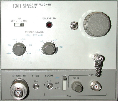
 A microwave sweep generator like the
HP 86222A has a lot in common with a tracking generator, but unlike
the real thing, used HP 8620-series sweeper plugins are commonly available on
eBay for a couple hundred bucks or less. It's worthwhile to explore the theory
of operation behind these less-expensive instruments to see what hidden
capabilities lurk beneath the surface of their spec sheets!
A microwave sweep generator like the
HP 86222A has a lot in common with a tracking generator, but unlike
the real thing, used HP 8620-series sweeper plugins are commonly available on
eBay for a couple hundred bucks or less. It's worthwhile to explore the theory
of operation behind these less-expensive instruments to see what hidden
capabilities lurk beneath the surface of their spec sheets!
The 86222A's block diagram is
shown below, including the ALC loop that keeps the output level constant across a large chunk of the RF spectrum.
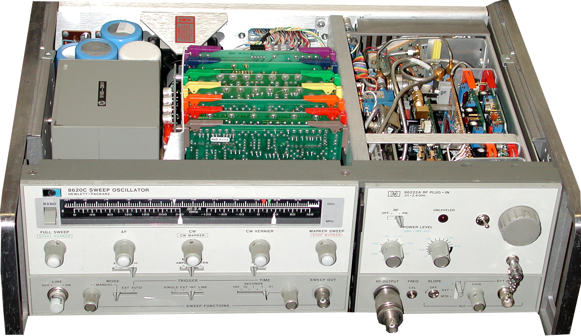
Like most of the other plugins for the popular HP 8620A/C sweeper mainframes,
the 86222A contains a swept YIG-tuned
oscillator (YTO) whose output is heterodyned with a fixed oscillator
to cover the frequency range of interest. In the 86222A's case, the output
frequency ranges from 10 MHz to 2.4 GHz.
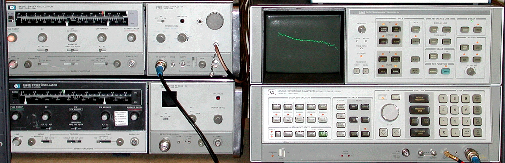
Users of the HP 8566 spectrum analyzers will immediately recognize the 86222A's
tuning range as a close fit for the 8566's own 0 - 2.5 GHz band. The similarities don't
end there: the 86222A's swept oscillator covers almost the same range
(3.8-6.3 GHz) as the 8566's own first LO (3.6-6.1 GHz). Its fixed source
is a 3.8 GHz cavity oscillator -- almost a match for the 8566's first IF
frequency of 3621.4 MHz in the 0-2.5 GHz band.
If the 86222A's 3.8-GHz oscillator
could be retuned to 3621.4 MHz and the 8566's first LO output substituted
for the 86222's YTO, then the output frequency would match the 8566's
displayed frequency at any given moment. We'd have a tracking generator!
 My immediate goal was to modify the HP 86222A to track my HP 8566B spectrum
analyzer while preserving its original functionality as a sweep generator.
Because my plugin was an A-suffix model without the marker assembly present
in the 86222B, there was a significant amount of unused space inside, as well
as plenty of room on the front panel for an SMA jack for the HP 8566B's
first LO connection and a switch to select tracking- or sweep-generator
functionality.
My immediate goal was to modify the HP 86222A to track my HP 8566B spectrum
analyzer while preserving its original functionality as a sweep generator.
Because my plugin was an A-suffix model without the marker assembly present
in the 86222B, there was a significant amount of unused space inside, as well
as plenty of room on the front panel for an SMA jack for the HP 8566B's
first LO connection and a switch to select tracking- or sweep-generator
functionality.
Using a surplus coax relay, it was easy enough to select the signal source for the 86222A's internal mixer. With the toggle switch in the down position, the 86222A's own YTO (A7 in the diagram above) is left in the circuit, and the 8620C/86222A combination operates as Messrs. Hewlett & Packard intended. Flip the switch up, and modulator/mixer U1 is driven by the HP 8566B's first LO instead. That leaves A6, the 3.8 GHz cavity oscillator, to be dealt with.
I took the oscillator apart and attempted to add a varactor diode to tune it between the required frequencies of 3.6214 GHz and 3.8 GHz, but the results weren't promising. It didn't appear possible to add enough capacitance to the cavity without shutting down the oscillator entirely. The required tuning range was just too great. Furthermore, stability might have been a problem when using the tracking generator in narrower analyzer spans. On the other hand, the requirement for a clean, stable, and tunable signal source was a great fit for the KE5FX/VK6BRO hybrid DDS/PLL synthesizer.
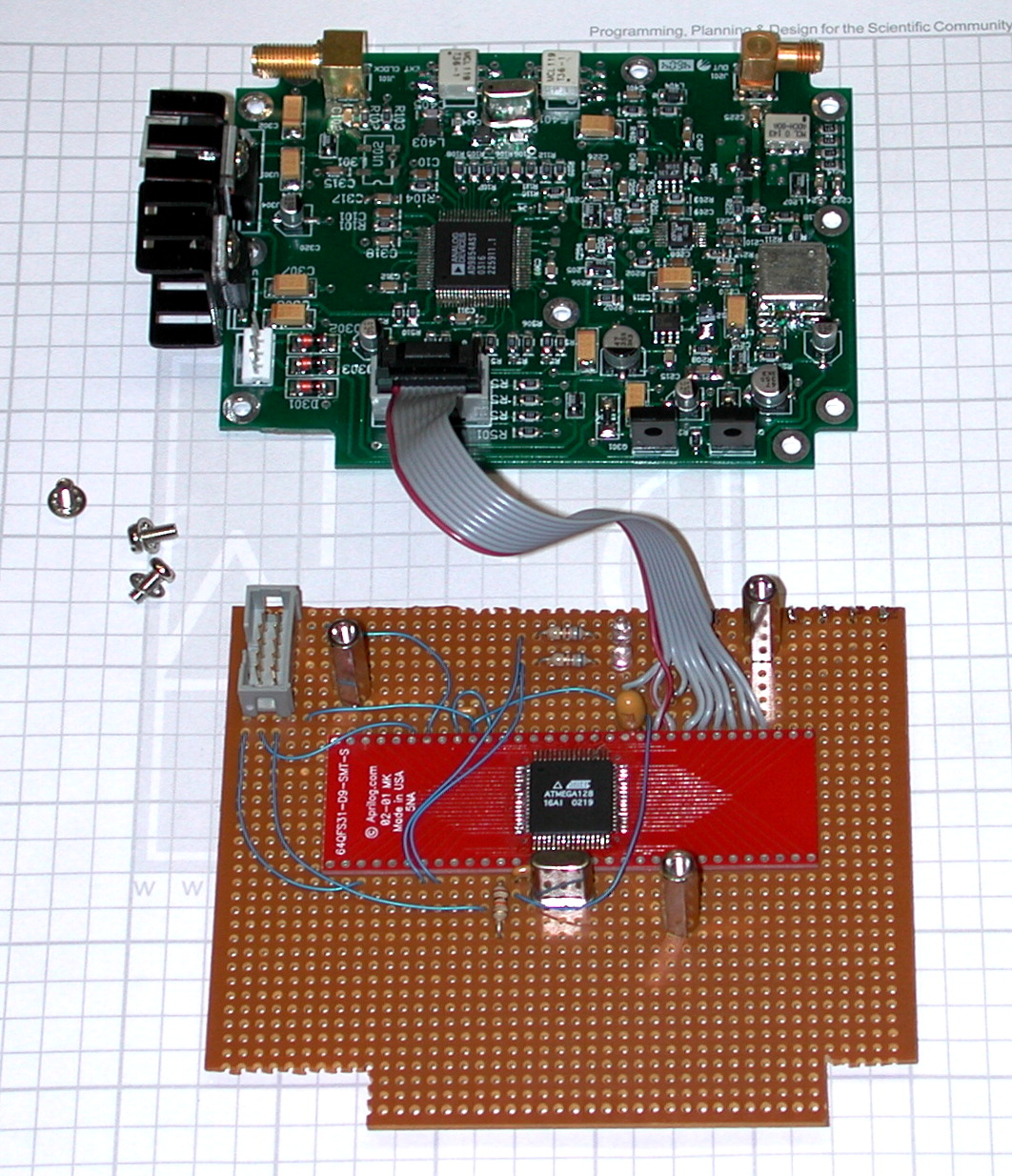
Ever since developing this general-purpose UHF/microwave synthesizer, I've found myself looking for excuses to use it in various projects. This was certainly a good excuse! I put together a synthesizer board with a 4.0-GHz ADF4113 PLL chip and a V900ME01 3.5-4.0 GHz VCO module from Z Communications. The 86222A offered plenty of room for a 'sandwich' assembly made from the PLL synthesizer board and a piece of perfboard with an Atmel ATmega128 microcontroller on it. The tab at the bottom of the microcontroller board fits into the edge connector reserved for the 86222B's marker assembly.
Source code and other files may be downloaded here (140K).
Because of normal variations in its crystal-filter center frequencies and other calibration-related issues, the spectrum analyzer's first IF frequency is never exactly on-target at any given resolution bandwidth. When using narrow resolution bandwidths, the frequency of the tracking generator's "fixed" oscillator must be tweaked to reflect these factors. Around 100 kHz of adjustment range either side of 3621.4 MHz is adequate.
It's easy to program the Atmel microcontroller to permit adjustment of the synthesizer's output frequency via an optical shaft encoder when the modified 86222A is in its tracking-generator mode. The optical encoder is a particularly good solution here -- it can be adjusted precisely at 1 Hz per 'tick' to optimize measurements made with the 8566B's 10 Hz filter, or spun quickly to find the peak response at wider resolutions.
A few additional details had to be handled, including the installation of
three-terminal 78xx-series regulators to power the synthesizer and
microcontroller, and a couple of attenuators to bring the signal levels
from the 8566B and DDS/PLL synthesizer within range of the 86222A's ALC loop.
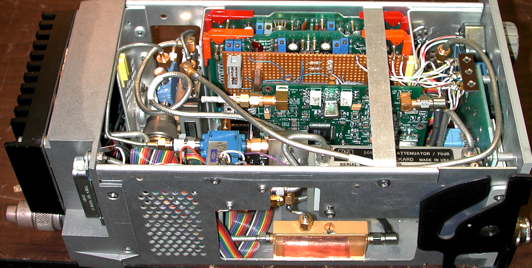
(In fact, the PIN modulator portion of mixer/modulator U1 in my plugin
was defective, requiring me to add an outboard modulator. This component is
visible just behind the 70 dB step attenuator on the 86222A's front panel in the
photograph below.) Overall ALC flatness is excellent (left).
Inadequate reverse isolation between a tracking generator and the analyzer's front end via its first-LO connection can cause baseline lift, reducing the usable dynamic range of measurements made with the generator. In this project, extra isolation in the first LO connection is provided by a 10 dB amplifier from the generous junk box of Bob Johnson, KF6KVG (at left) and a coupler supplied by Chuck Houghton, WB6IGP. Thanks are due to Bob and Chuck, as well as Wil Jensby, W6EOM (right) for their help "tracking" down parts for this project!