 After spending most of the winter of 1998 bringing my newly-acquired Tektronix 492 spectrum analyzer back from Murphy's door, my
test-equipment budget was showing signs of even more serious disrepair. Now that the 492 was up and running, I wanted to use it to evaluate
the frequency response of filters, amplifiers, and other two-port RF devices, but I couldn't seem to locate any affordable examples of the
492's companion TR 503 tracking generator on the surplus market.
After spending most of the winter of 1998 bringing my newly-acquired Tektronix 492 spectrum analyzer back from Murphy's door, my
test-equipment budget was showing signs of even more serious disrepair. Now that the 492 was up and running, I wanted to use it to evaluate
the frequency response of filters, amplifiers, and other two-port RF devices, but I couldn't seem to locate any affordable examples of the
492's companion TR 503 tracking generator on the surplus market. Tucker's price of $2000 for a reconditioned TR 503 was almost as much as I'd paid for the 492 itself. Clearly, I'd have to find another solution.
Taking into account some assorted odds and ends from Mini-Circuits
that were already lying around the shack, I was able to scrape together enough junk to build a tracking generator that would compete very respectably with
Tektronix's own offering.
My usual habit of enclosing individual RF circuits in their own Hammond 1590-series boxes served me well in this project. It's hard to imagine
a system in which good isolation and shielding techniques are more important than in a spectrum analyzer / tracking generator combination.
As Wes Hayward, W7ZOI suggests in his own spectrum-analyzer project notes,
the extremely high dynamic range and wide frequency response of these instruments are perfect for revealing all the places where you've been sloppy in your RF
construction practices.
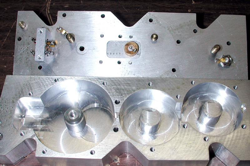
Frequency response and insertion loss of modified HP 8555A bandpass filter
In operation, the 110 MHz signal from the synthesizer is mixed
with the 492's 2182 MHz 2nd LO. The unwanted mixer product at 2292 MHz is eliminated by the salvaged HP8555A cavity filter, while the desired 2072 MHz
sideband is passed on to a second mixer. There, the 2072 MHz signal is combined with the 492's 2072-3872 MHz 1st LO to yield the tracking generator's
final output frequency.
The 110-MHz PLL's reference signal is provided by a 2N2222-based crystal oscillator which can be pulled with a varactor a few hundred hertz
to either side of 5.5 MHz, allowing the output frequency to be adjusted precisely to conform to the instrument's exact 3rd IF frequency. The reference
VCXO and its associated buffer amplifiers occupy the rightmost 1/3 of the 4x2x1" Hammond enclosure.
Initial tests revealed the Colpitts VCO to be vulnerable to severe FM microphonic effects due to the "dead bug" construction style. Suspending
oscillator tank-circuit components in midair by their leads is not exactly good engineering practice, but space considerations ruled out a proper
coil-mounting solution in this case. Fortunately, tweaking the lag/lead filter for a wider loop bandwidth effectively got rid of
all traces of microphonic problems, making for a dramatic demonstration of PLL action. As soon as I was able to pound on the Hammond enclosure
with a screwdriver without hearing a loud ringing sound in a nearby receiver, I knew I had the loop filter cutoff frequency dialed in properly.
Who says you need two semesters of control theory to get a PLL working? :-)
The synthesizer exhibits good spectral purity for this application, with combined phase/amplitude
noise of approximately -109 dBc/Hz at a 10-kHz offset. Its VCXO reference is not very stable close to the carrier,
but this isn't a concern here.
5.5 MHz reference VCXO
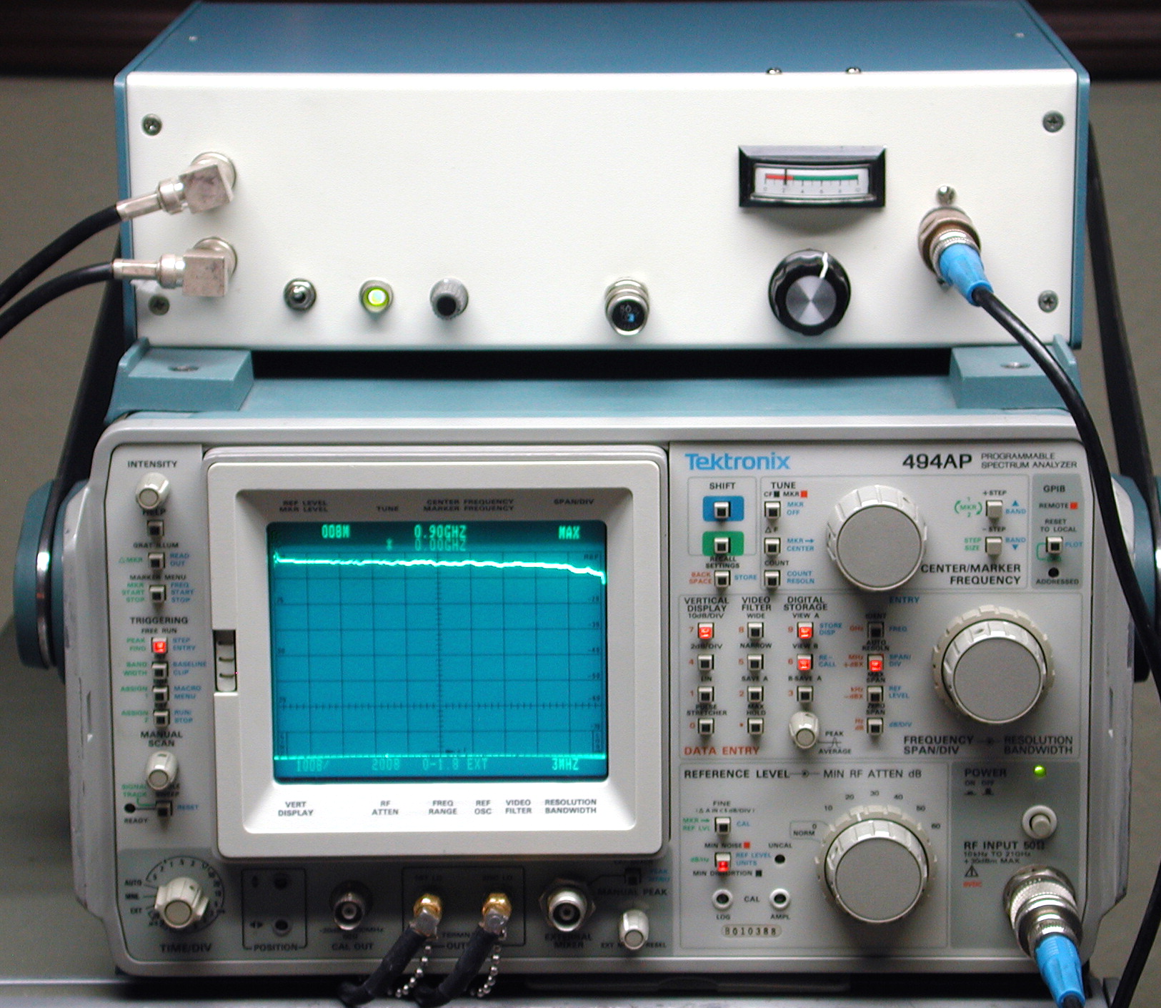
At left is a 2 dB/division display of the trace visible in the top photograph on this page (which was taken at 10 dB/division). In this shot, the
tracking generator is connected to the 492 via two inexpensive BNC female-to-N male coax adapters and about 3 feet (1M) of Radio Shack-grade RG-58 coax.
At right is the same measurement taken with nothing but an N barrel connector between the analyzer and generator. (I've adjusted the
tracking-generator output level control slightly to "normalize" both scans to the same level at 900 MHz.)
With the two coax adapters and RG-58 jumper in the signal path, a noticeable falloff starts to occur in the system's frequency response at a few
hundred MHz. The left trace is about 1 dB down at 900 MHz, relative to its counterpart on the right. By 1800 MHz, an additional 2 to 3 dB of loss can
be observed at left. This may not seem like a large variation across such a wide frequency span, but it was enough to make me concerned that I wasn't
meeting Tektronix's flatness specs for the TR 503! Either that, or my prized 492's amplitude response was out of calibration.
Fortunately, the only problem I really had was taking the high-frequency characteristics of my coaxial interconnects for granted.
Later, a high-quality RF power meter connected directly to the tracking generator revealed that its actual frequency response
was within +/- 1.5 dB between 100 kHz and 1800 MHz, safely within the TR 503's specifications (per the 1990 Tek catalog) of +/- 2.25 dB over the same
span. Almost all of the flatness error manifested itself as loss above 1200 MHz, due, I suspect, to operating the Wiltron output-level sampler beyond its
frequency ratings.
September 9, 2009 Updated the page with some better photos and fixed some broken links.
In response to numerous emails over the past few years, it's worth noting that this page cannot, and should not, be seen as a recipe to be followed exactly. If you decide to build a tracking generator,
your own collection of spare parts, test equipment, and RF skills will determine how it's built and how it performs. Because of my reliance on surplus parts and ad-hoc layouts, you won't be able to duplicate this design exactly... nor, from the
vantage point of 10+ additional years of RF experience on my part, should you. :) The design would differ in several respects if I were undertaking it today.
For this reason, I'm not providing detailed gain-distribution figures, parts lists, isolation measurements, and other specifics. Apart from a few notes in the
block diagram, these records don't exist, and wouldn't be very helpful if they did. Instead, you can look forward to the experience of
discovering the capabilities and limitations of your own junk box!
June 13, 2013 Here's a link (3 MB .PDF) to TekScopes volume 7 issue 5, published in 1975, in which Fred Telewski of Tektronix describes the new TR 502/TR 503 and its block diagram in detail.
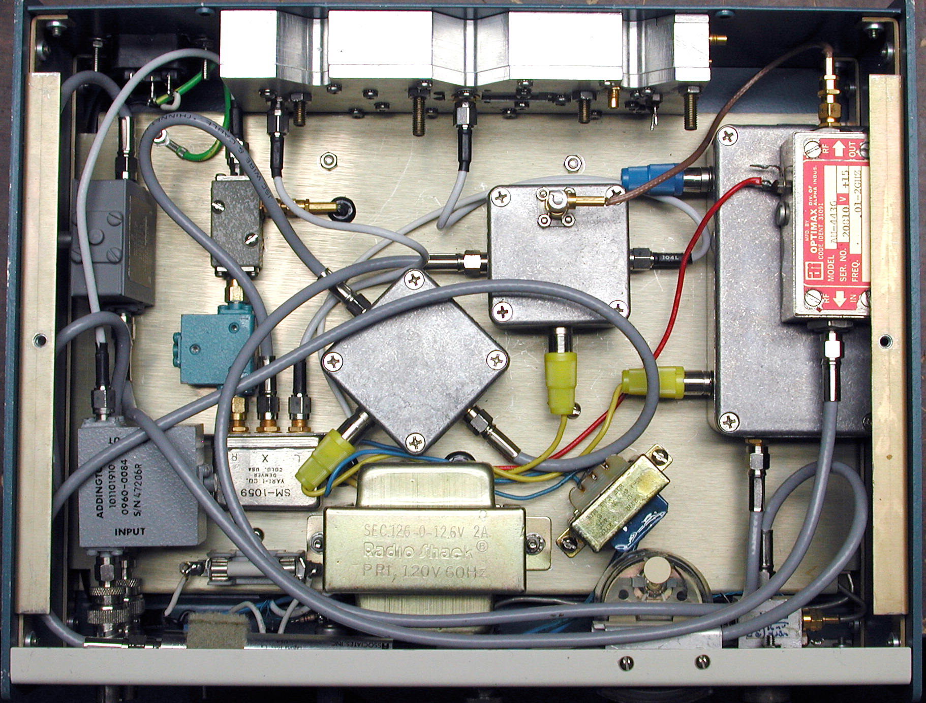 Initially the idea of homebrewing a tracking generator hadn't occurred to me, but the more I stared into the junk box, the more it started to make
sense. I'd recently stripped an old Wiltron sweep-generator plugin module for parts, salvaging an exotic-looking microwave mixer, PIN modulator, and
output sampler, along with a broadband amplifier module and a couple of directional isolators. A defunct HP8555A spectrum analyzer contributed a
very nice tunable cavity bandpass filter as well as another isolator or two.
Initially the idea of homebrewing a tracking generator hadn't occurred to me, but the more I stared into the junk box, the more it started to make
sense. I'd recently stripped an old Wiltron sweep-generator plugin module for parts, salvaging an exotic-looking microwave mixer, PIN modulator, and
output sampler, along with a broadband amplifier module and a couple of directional isolators. A defunct HP8555A spectrum analyzer contributed a
very nice tunable cavity bandpass filter as well as another isolator or two. Notes
Closeup photos of exterior and interior of modified HP 8555A bandpass filter
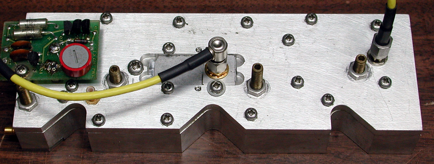
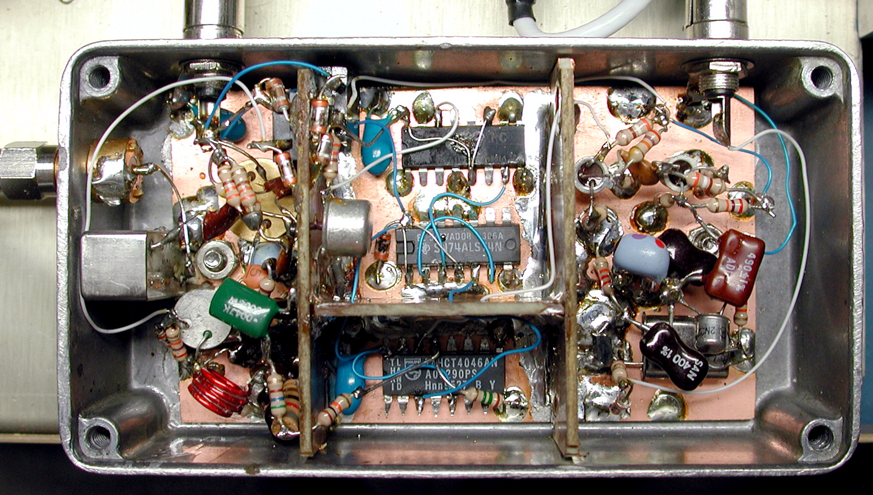 Here's a closeup of the only complex part of the tracking generator -- the 110 MHz PLL synthesizer subassembly. This synthesizer is responsible for
generating an offset signal to cancel out the 110 MHz 3rd IF conversion in the 492's signal chain.
Here's a closeup of the only complex part of the tracking generator -- the 110 MHz PLL synthesizer subassembly. This synthesizer is responsible for
generating an offset signal to cancel out the 110 MHz 3rd IF conversion in the 492's signal chain.
The synthesizer's main VCO,
visible at lower-left, is a 110-MHz Colpitts oscillator based on a 2N5109. Its output is divided by 20 by a 74F190 and 74HCT74 (center, top) and
fed to a 74HCT4046 phase/frequency detector which compares the divided VCO output with the 5.5 MHz crystal oscillator reference. The 74HCT4046's
charge pump output maintains phase lock by steering the 110 MHz VCO via a passive lag/lead-type loop filter.
Schematics
Frequency divider, phase detector, and loop filter
110 MHz VCO and output buffer
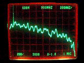
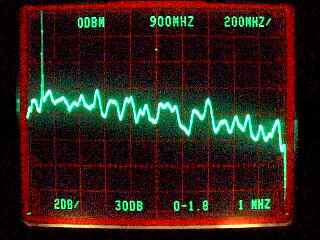 These two images demonstrate the frequency-versus-amplitude flatness achieved by the tracking generator / Tek 492 combination. Both were taken with
identical spectrum-analyzer settings, displaying the RF spectrum from DC to 1800 MHz at 2 dB per vertical division. I've put side-by-side
screenshots on the page to illustrate an interesting application for the tracking generator: evaluating the quality of RF-grade interconnects.
These two images demonstrate the frequency-versus-amplitude flatness achieved by the tracking generator / Tek 492 combination. Both were taken with
identical spectrum-analyzer settings, displaying the RF spectrum from DC to 1800 MHz at 2 dB per vertical division. I've put side-by-side
screenshots on the page to illustrate an interesting application for the tracking generator: evaluating the quality of RF-grade interconnects.
May 29, 2004 The tracking generator is compatible with any spectrum analyzer in the Tek 490- and 2750-series lineups, including the 494AP I use today. A subsequent comparison shows the difference between a 6' length of 1/2" Heliax and a high-quality 4' BNC-BNC cable with two BNC-N adapters. Almost 2 dB of loss can be seen at the 1.8-GHz end of the range.
Copyright © 2000 John Miles. All rights reserved.