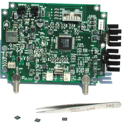
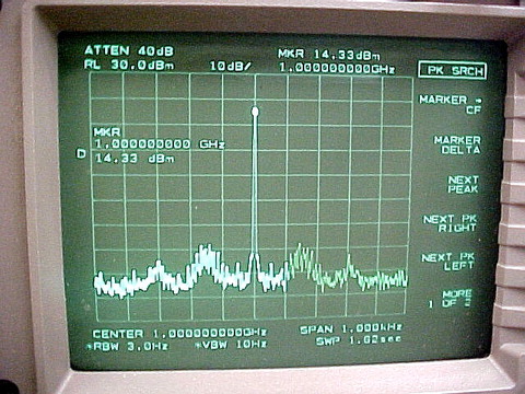
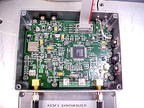
Four ICs pack tremendous power and flexibility into a 4" Hammond 1590-series chassis. Controlled by the PC parallel port, this hybrid DDS/PLL synthesizer delivers full-octave coverage between 1000 and 2000 MHz with sub-1 Hz resolution and commercial-quality phase-noise performance.
Icom IC-R7000 first LO synthesizer: -51.5 dBc/Hz at 250 Hz
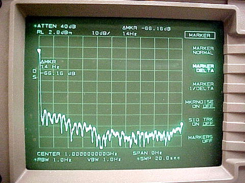
KE5FX hybrid synthesizer: -80.3 dBc/Hz at 250 Hz
Icom IC-R7000 first LO synthesizer: -70.5 dBc/Hz at 1 kHz
KE5FX hybrid synthesizer: -83.7 dBc/Hz at 1 kHz
Icom IC-R7000 first LO synthesizer: -99.9 dBc/Hz at 10 kHz
KE5FX hybrid synthesizer: -91.9 dBc/Hz at 10 kHz
1500 Hz loop bandwidth: -81.5 dBc/Hz at 250 Hz
2500 Hz loop bandwidth: -80.3 dBc/Hz at 250 Hz
3500 Hz loop bandwidth: -82.3 dBc/Hz at 250 Hz
1500 Hz loop bandwidth: -79.3 dBc/Hz at 1 kHz
2500 Hz loop bandwidth: -83.7 dBc/Hz at 1 kHz
3500 Hz loop bandwidth: -84.9 dBc/Hz at 1 kHz
1500 Hz loop bandwidth: -93.9 dBc/Hz at 10 kHz
2500 Hz loop bandwidth: -91.9 dBc/Hz at 10 kHz
3500 Hz loop bandwidth: -87.9 dBc/Hz at 10 kHz
Icom IC-R7000 first LO synthesizer VCO tuning line, 770 MHz to 1030 MHz
Icom IC-R7000 first LO synthesizer VCO tuning line, 1030 MHz to 770 MHz
KE5FX hybrid synthesizer VCO tuning line, 1000 MHz to 2000 MHz
KE5FX hybrid synthesizer VCO tuning line, 2000 MHz to 1000 MHz
Improved spur performance (see spur-search results below) is obtained with an inexpensive monolithic crystal filter following the AD9854 DDS. This graph shows the DDS coverage range overlapped with the crystal filter's close-in response in an early prototype.
| IDC Connector | LPT Port | AVR Port 'A' Signal |
|---|---|---|
| 1 | 15 | PA0 |
| 2 | 9 | PA1 |
| 3 | - | - |
| 4 | 6 | PA2 |
| 5 | 7 | PA3 |
| 6 | 8 | PA4 |
| 7 | 4 | PA5 |
| 8 | 2 | PA6 |
| 9 | 3 | PA7 |
| 10 | 18-25 | GND |
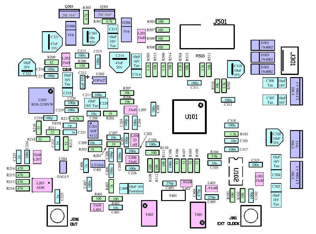
Complete parts list including Digi-Key, Mini-Circuits, and Analog Devices part numbers
R101: 1.3K ohms (P1.3KECT-ND)
R102, 103: 100 ohms (P100ECT-ND) (50-ohm external clock input only)
R102, 103: 1K ohms (P1.0KECT-ND) (Internal clock source only)
R403: 1K ohms (P1.0KECT-ND)
R104: 3.9K ohms (P3.9KECT-ND)
R105-108, 212: 51 ohms (P51ECT-ND)
R201-203: 18 ohms (P18ECT-ND)
R206, 207, 510-514: 10K ohms (P10KECT-ND)
R210, 211, 218: 22 ohms (P22ECT-ND)
R213-216: 470 ohms (P470ECT-ND)
R217: 4.7K ohms (P4.7KECT-ND) (ADF4112 PLL chip only; omit for LMX2326)
R301, 303: 4.7K ohms (P4.7KECT-ND)
R401, 402, 501, 507-509, 109-112: 100 ohms (P100ECT-ND)
R502-506: 3.3K ohms (P3.3KECT-ND)
C101, 103, 207, 208, 209, 401: 0.01 uF/50V ceramic (399-1234-1-ND)
C102, 104, 106, 202, 204, 205, 211, 215, 219, 224, 226, 309, 311, 312, 315,
317, 318, 407, 408: 0.1 uF/50V ceramic (PCC104BCT-ND or 311-1179-1-ND)
C201, 203, 206, 210, 217, 220: 100 pF/50V ceramic (399-1205-1-ND)
C214, 321: 47 uF/35V electrolytic (PCE3280CT-ND)
C218, 228, 302, 304, 307, 308, 313, 314, 409: 10 uF/16V tantalum
(399-1595-1-ND or 399-3732-1-ND)
C221-223, 225, 406: 0.001 uF/50V ceramic (PCC102BCT-ND or 311-1170-1-ND)
C230: 1 pF/50V NPO ceramic (399-1178-1-ND) (see text)
C301, 319, 320, 322: 10 uF/35V electrolytic (PCE3413CT-ND)
C403, 405: 270 pF/50V NPO ceramic (399-1209-1-ND)
C404: 470 pF/50V NPO ceramic (399-1213-1-ND)
D301-303: 1N4002 (DL4002DICT-ND)
D304: 5.6V 500 mW Zener (BZT52C5V6-FDICT-ND)
D306: 5.6V 500 mW Zener (5V VCOs only) (BZT52C5V6-FDICT-ND)
D306: 12V 500 mW Zener (12V VCOs only) (BZT52C12-FDICT-ND)
F401: ECS-10.7-15B monolithic crystal filter, +/- 7.5 kHz bandwidth, 25 kHz stopband
(X704-ND)
J101, 201: SMA female bulkhead jack (J569-ND)
J301: 4-position straight header (A1912-ND or A1922-ND)
J501: 10-position shrouded header (MHB10K-ND)
L402,403: 0.91 uH RF choke (DN1015CT-ND)
L201, 202, 204-207, 301, 404: 22 uH - 39 uH 115 mA RF choke (TKS2638CT-ND, TKS2639CT-ND, or
445-1741-1-ND)
L203: Mini-Circuits ADCH-80A
Q301, 303: 2SC1847 (2SC18470Q or MJE182)
T401, 402: Mini-Circuits T36-1-KK81 36:1 RF transformer
U101: Analog Devices AD9852AST DDS synthesizer
(AD9852AST also available from Digi-Key)
U102: Clock module for internal-clock option (ECS-3953M)
U201: Analog Devices ADF4112BRU 3.0 GHz RF PLL frequency synthesizer
(also available from Digi-Key)
U201: National Semiconductor LMX2326TM 2.8 GHz RF PLL frequency synthesizer
(LMX2326TM-ND)
U202: Burr-Brown OPA27 low-noise operational amplifier (OPA27GU-ND)
(Update: LT1677 recommended instead of OPA27)
U203: Mini-Circuits ROS-2150VW 1-2 GHz VCO
U204: Mini-Circuits GALI-5 monolithic amplifier
U301, 302: Linear Technology LT1086-3.3 voltage regulator (LT1086CT-3.3-ND)
U304: 7812 voltage regulator (NJM7812FA-ND)
U401: Linear Technology LT1016 precision comparator (LT1016CS8-ND)
Miscellaneous hardware and optional parts
Hammond 1590BB aluminum enclosure (HM152-ND)
TO-220 mounting kits for U301, U302 (4724K-ND)
10-position IDC socket for J501 (MKC10A-ND)
10-position ribbon cable (MC10G-5-ND
Loop filter components (ROS-2150VW VCO, 2.5 kHz loop bandwidth):
R208: 150 ohms (P150ECT-ND)
R209: 82 ohms (P82ECT-ND)
C212: 1 uF/35V tantalum (PCS6105CT-ND) or 478-1671-1-ND)
C213: 0.1 uF/50V ceramic (PCC104BCT-ND or 311-1179-1-ND)
C216: 0.1 uF/50V ceramic (PCC104BCT-ND or 311-1179-1-ND)
Full-size PCB layout (300 kB .JPG, courtesy Jorge Castano)
Mechanical drawing (90 kB .PDF, courtesy Steven Bible, N7HPR)
Thanks to Richard Hosking, VK6BRO for his schematic-drafting work and design suggestions!
AutoTrax .PCB file (by Richard Hosking) -- tested and working with components above
Microsoft Works spreadsheet for loop-filter design (by Richard Hosking)
Miscellaneous Atmel assembly routines for AD9852 and related components (by Richard Hosking)
Random spur search results for 25 kHz crystal filter following DDS, 10 MHz clock with adaptive multiplier (8-12X) algorithm, 5000 samples (20MB)
No significant spurs at any of 5,000 randomly-selected frequencies
Unzip each of the above files into separate, empty directories and run HPGLVIEW.EXE to browse spectrum-analyzer plots -- or download the current version of the HP-GL/2 tools (highly recommended!)
Cross-platform Atmel/Win32 C++ control software, with source
As published in QEX/Communications Quarterly, March/April 2004. Text and figures reproduced by permission.
article.pdf (Adobe .PDF format, 650KB)
article.doc (MS Word 97 format, 335KB)
Errata and Updates
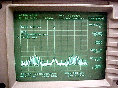
November 3, 2003 - Miguel Llanes of Rockwell-Collins sends along a few shots of his synthesizer PCB and
its performance as characterized on an HP 8563E spectrum analyzer. This FFT-based instrument delivers better
close-in measurement performance than the Tektronix 494AP used to capture the screenshots
at the top of the page.
February 29, 2004 Digi-Key now appears to be stocking both the Analog Devices AD9852ASQ DDS and ADF4112 PLL chips. I've updated the parts list accordingly.
March 20, 2004 The third edition of Dean Banerjee's PLL Performance, Simulation, and Design is now available at Amazon. I've just received my own copy -- it's a substantial revision that's well worth owning for those interested in PLL analysis and experimentation.
March 20, 2004 Release 2.00 of the control/test software contains versions of ASTEST.EXE and NSTEST.EXE compatible with NT-based versions of Windows such as Windows 2000 and Windows XP. An MS-DOS version, compiled with the free OpenWatcom C++ compiler, is also included.
March 21, 2004 In figure 11 on page 17, U102 pin 4 should be connected with a dot to the 3V3A line. Thanks to Steven Bible, N7HPR (who also contributed a nice assembly drawing) for this correction.
March 21, 2004 I've created a Yahoo Group for discussion of this project and other projects on the KE5FX site. Click the link to sign up!
March 21, 2004 A few builders have encountered trouble with latchup when running from the PC parallel port. When testing my own boards, I usually avoid these problems by (a) connecting the parallel port only after the PC has booted into Windows; and/or (b) making sure that power is applied to the synth board before the PC goes through its BIOS power-up sequence.
The latchup problem seems to occur when one or more parallel port signals supply enough voltage through the PLL chip's ESD protection diodes to power up the chip in the absence of a valid Vcc supply. By the time power is applied, the chip is already in a state that prevents it from being initialized by the software. At that point, the only way to restore proper operation is to disconnect both the power supply and the LPT port from the board.
March 22, 2004 Peter Chadwick, G3RZP, writes, The authors state that phase noise is typically -140 dBc/Hz for ECL technology. This is generally true, although -140 dBc/Hz can be bettered with ECL -- Plessey Semiconductors put some effort into producing some very low phase noise ECL dividers in a collaborative effort with what was Marconi Instruments, back some 15 or so years ago. The SP8402, which is now made by Zarlink Semiconductor, typically runs -155 to -160 dBc/Hz at 1 kHz offset. CMOS can be very good, although the move to lower voltages doesn't necessarily help. Gallium Arsenide is very poor because of the 1/f noise, although even that has improved considerably in the last 20 years or so. Thanks to Peter for the clarification.
March 23, 2004 Interested in a kit of parts for the synthesizer? If so, Steven Bible, N7HPR would like to hear from you. Details of the cost, contents, etc. will be determined based on the level of interest.
March 25, 2004 Matthew Potter, KG4JZH suggests that some of the Mini-Circuits parts can be replaced with sample components from Sirenza Microdevices. According to Matthew, Here is the Sirenza samples request form (400 KB MS Word); they also make Vari-L VCOs. I think you could also subsitute the GALI-5 MMIC with a Sirenza equivalent, although you might have to change some of the bias components for the Sirenza part. Last year Sirenza was giving out a three ring binder full of MMICs and PCBs as a designers kit... see if they are still offering it. Sirenza has a liberal samples policy!
May 1, 2004 A couple of useful links:
November 17, 2004 Added alternate Digi-Key part number for 33 uH chokes. These appear to be back-ordered indefinitely, so I've specified a 39 uH part which is currently in stock.
A new batch of PC boards has just arrived, so the PayPal link is again open for business.
November 27, 2004 I've added a brief page describing some experimental results with a phase-locked Gunn source at 10 GHz.
April 16, 2005 Here's a phase-noise log plot taken at Microwave Update 2004 on
an HP 8563E / HP 85671A workstation.
April 20, 2005 Some observations of relative
flatness with three different Mini-Circuits MMICs at U204.
Graphs are uncorrected for analyzer and interconnect characteristics.
GALI-5 with 470-ohm resistors at R213-216
GALI-59 with 390-ohm resistors at R213-216
GALI-74 with 330-ohm resistors at R213-216
July 3, 2005 New V2.10 control/test software released. See the enclosed readme.txt file for a list of changes from the previous version.
In some recent experiments with the Linear Technology LT1128 opamp, I've observed 1-2 dB of improvement in the synthesizer's composite noise at 10 kHz from the carrier and beyond. Low-bandwidth loops, or those using more-sensitive VCOs such as the UMS-2150-R16 from Universal Microwave, will benefit the most from a quieter opamp. The LT1128 is somewhat expensive compared to the OPA27 and LT1677 parts I've been using, but if your application is noise-sensitive it may be worth a look. It can be ordered from DigiKey under the LT1128CS8-ND part number.
The major drawback to the LT1128 (besides its $9 price tag) is that it is not well-behaved when its output is driven near its supply rails. Latchup and oscillation are virtually guaranteed when the synthesizer is tuned too close to its limits, with complete disconnection of power and I/O being necessary for recovery.
The best overall opamp choice for most purposes appears to be the Linear Technology LT1677, also available from DigiKey as LT1677CS8-ND. The LT1677 is a true rail-to-rail replacement for the OP27 family. The LT1677 is not only very quiet, but it's immune to the latchup and instability problems that other opamps can exhibit.
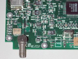 November 23, 2005 You can improve the synthesizer's in-band phase noise by 1-2 dB by
eliminating T402, the 36:1 transformer at the output of the crystal filter. Replace it with a straight piece of wire as shown in the
photo at right, and replace R401, R402, and R403 with 9.1K resistors (DigiKey P9.1KECT-ND).
This is not a mandatory modification, but it does improve the signal level at the comparator input while saving a few dollars
on the second transformer.
November 23, 2005 You can improve the synthesizer's in-band phase noise by 1-2 dB by
eliminating T402, the 36:1 transformer at the output of the crystal filter. Replace it with a straight piece of wire as shown in the
photo at right, and replace R401, R402, and R403 with 9.1K resistors (DigiKey P9.1KECT-ND).
This is not a mandatory modification, but it does improve the signal level at the comparator input while saving a few dollars
on the second transformer.
Also, I've found that the UMS-2150-R16 VCO from Universal Microwave mentioned above is more reliable at high operating temperatures if you make a few changes to its output matching network. If you use the UMS-2150 in your synthesizer, you'll need to increase R211 from 22 ohms to 220 ohms to avoid overdriving the PLL chip's VCO input. Then, solder a 100-ohm resistor directly across the VCO output and neighboring ground connections to maintain a good broadband load. Without it, the GALI-5's input will dominate the VCO's load impedance -- an invitation to harmonic-locking problems.
Like the T402 modification, the additional VCO load resistor is visible in the photo at right.
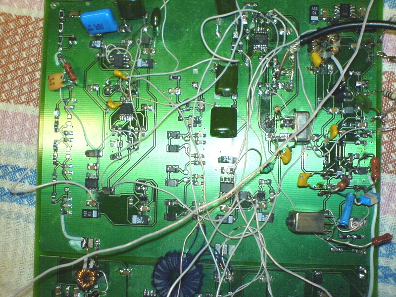
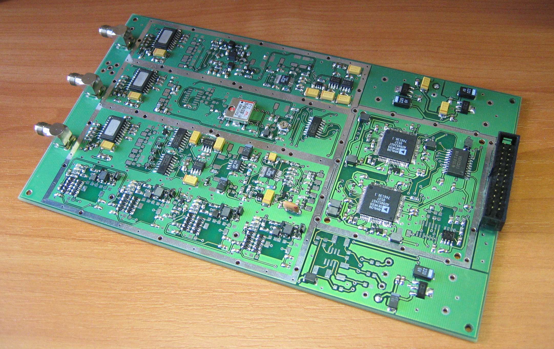
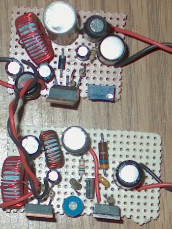
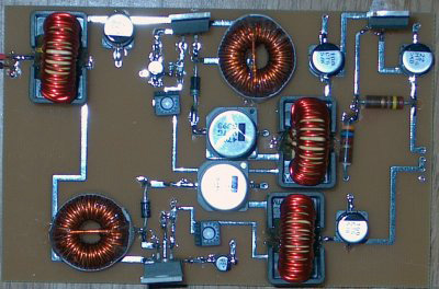
January 18, 2006 Genadi Zawidowski (ex-UA1ARN) sends along some photos of his own hybrid synthesizer design(s):
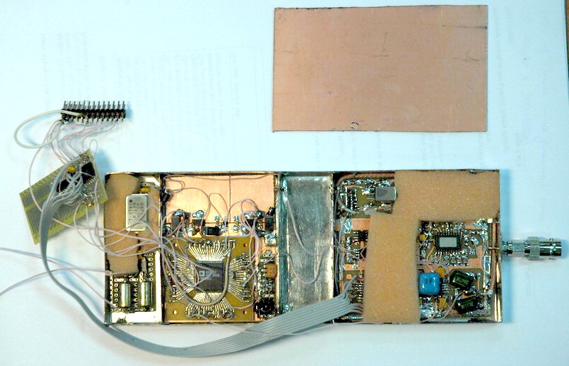
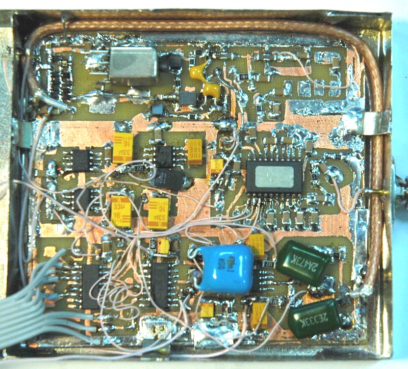
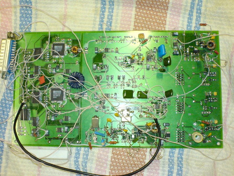
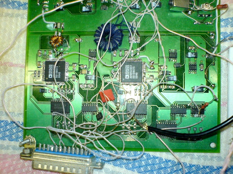
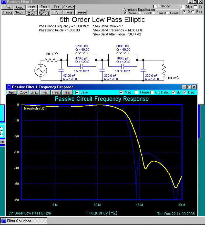
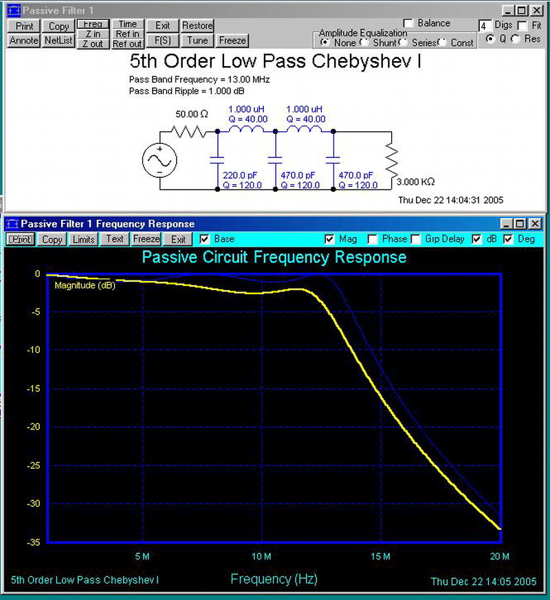
Genadi was also kind enough to offer a couple of alternative low-pass matching networks that can eliminate T401. By combining this modification with the T402 replacement above (November 23, 2005), you can eliminate both T36-1 transformers if you prefer.
Both elliptic and Chebychev versions are shown below; either should work fine in practice. They replace all of the components from C403 through T401.
April 7, 2006 Ed Johnson, AD5MQ, has designed a nice boost-regulated supply that converts +12V to the +15 and +20V levels needed by the synthesizer.
Ed's project page, which includes a BOM and Gerber files for his power-supply project, can be found here.
In other news, I'm all out of PC boards, and I'm planning to wait awhile before ordering any more. Due to the ongoing implementation of the European Union's RoHS (Reduction of Hazardous Substances) directive, the entire electronic component industry is in a state of (lead-free) flux, and it's proving difficult for builders to find some of the parts for the synthesizer. In most cases, components that appear to be out of production are actually still available, but must be ordered under new part numbers that reflect their lead-free versions. Meanwhile, suppliers such as Digi-Key are struggling to keep up with a deluge of inventory revisions. You can expect some significant "link rot" in the parts list while these issues are being sorted out.
This situation won't last forever, but it will be at least a few months before I feel comfortable bringing the BOM up to date and ordering more boards. Consequently, I've removed the PayPal link for the time being.
June 14, 2006 PC boards are available once again. The PayPal link has been re-enabled, and the parts list has been updated where necessary with RoHS-compliant part numbers. All parts except the LMX2326 and OPA27 chips are available as of this writing; recommended substitutes for these are the ADF4112 and LT1677, respectively.
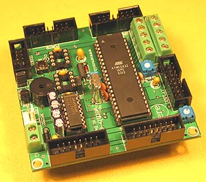
September 12, 2006 I receive quite a bit of mail from people asking for pointers to Atmel AVR development boards and prototyping solutions for standalone synthesizer implementations. About a year ago, I put together a couple of self-contained synthesizers for a friend that used ATMega32-based control boards from Futurlec, a 16x2 backlit LCD from the same vendor, and a 4x3 numeric keypad from DigiKey.
 The C++ software for that project, compilable with the WinAVR AVR-GCC package, may be downloaded
here (1 MB). The main module, pari.cpp, implements a simple, intuitive user interface
that can recognize and control multiple synth boards, keep track of configuration settings using the ATMega32's on-chip NVRAM, and generate both CW
and swept signals. It makes a great starting point for your own embedded applications... or the code can be used as-is, if you don't mind studying
the comments to figure out the port assignments for the keypad, LCD, and synthesizer!
The C++ software for that project, compilable with the WinAVR AVR-GCC package, may be downloaded
here (1 MB). The main module, pari.cpp, implements a simple, intuitive user interface
that can recognize and control multiple synth boards, keep track of configuration settings using the ATMega32's on-chip NVRAM, and generate both CW
and swept signals. It makes a great starting point for your own embedded applications... or the code can be used as-is, if you don't mind studying
the comments to figure out the port assignments for the keypad, LCD, and synthesizer!
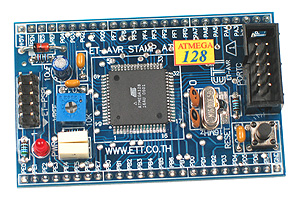 Futurlec's newer ET-AVR Stamp module based on the ATMega128 looks ideal as well. At
approximately US $20 for a fully-populated board, you sure can't argue with the price. I would probably go with the ET-AVR Stamp if I were building
an AVR application today.
Futurlec's newer ET-AVR Stamp module based on the ATMega128 looks ideal as well. At
approximately US $20 for a fully-populated board, you sure can't argue with the price. I would probably go with the ET-AVR Stamp if I were building
an AVR application today.
Incidentally, FuturLec is a great economy-priced parts house for hobbyist/low-volume R&D work. It's rapidly becoming one of my favorites.
July 17, 2007 The last order of 50 PC boards from Australia has been depleted. I'm going to 'retire' this project in favor of a new version, to be designed later this year. An announcement will be posted to the KE5FX Yahoo Group when the new boards are available.
Anticipated features for the next-generation hybrid synthesizer include:
I will probably also include space on the board for an optional Atmel controller that will allow the synthesizer to respond to high-level commands issued via RS-232, for easier integration with existing projects.
Special thanks to everyone who has ordered boards, built the synthesizer, and contributed to its development and refinement!
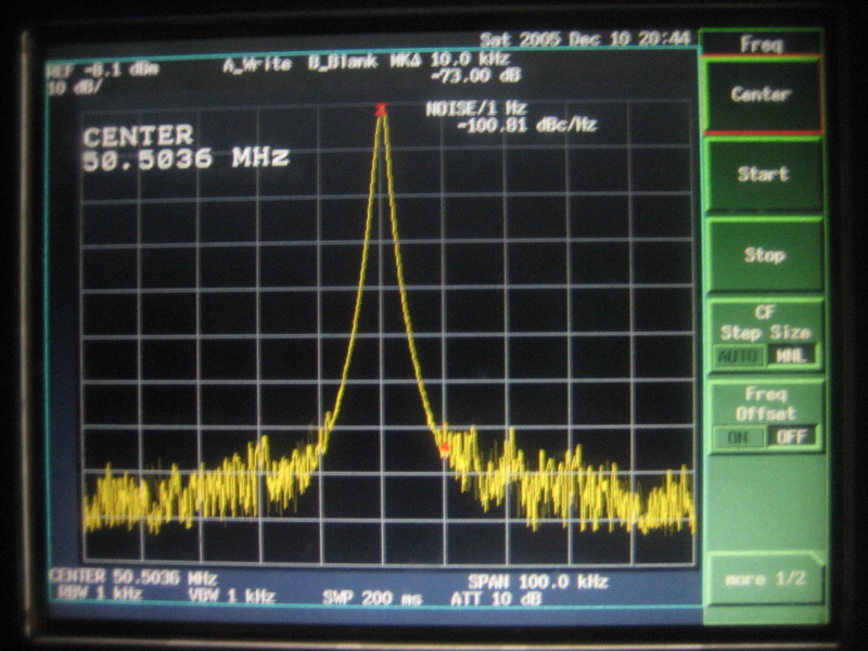
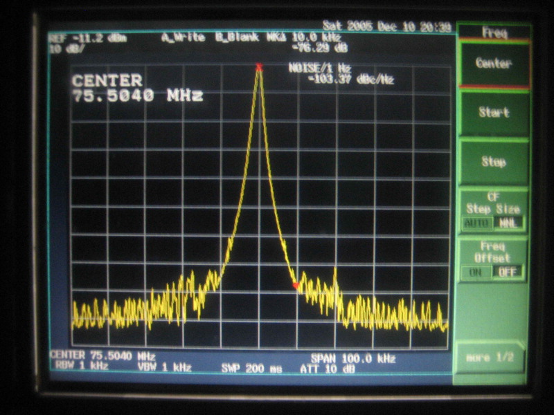
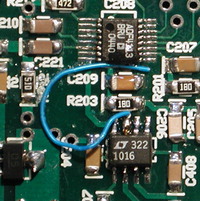
July 22, 2007 You can reduce the 10.7 MHz sidebands that result from coupling of DDS energy from the LT1016 into the output amplifier circuit by adding a small "gimmick" wire from the LT1016's inverting output (pin 7) that rests on or just above the PC board. Careful manipulation of the wire while watching the sidebands on a spectrum analyzer is necessary to avoid making things worse! In this case, the sidebands were improved from roughly -57 dBc to -73 dBc:
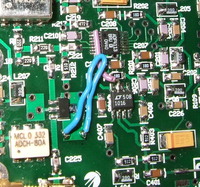
Eddie, DL2SEP, reports that an additional grounded loop (bottom photo above) enabled him to reduce the unwanted sidebands to -85 dBc.